- 您现在的位置:买卖IC网 > Sheet目录222 > DS1977-F5# (Maxim Integrated)IBUTTON EEPROM 32KBit F5
�� �
�
 �
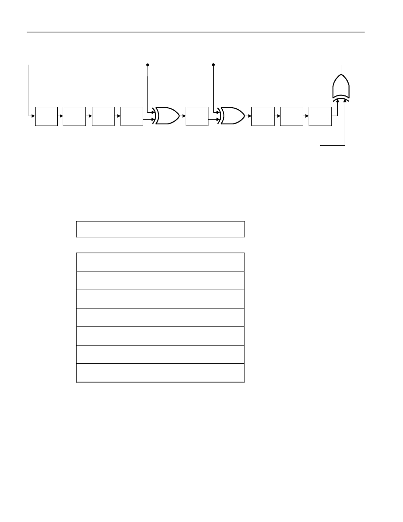
�POLYNOMIAL� =� X� +� X� +� X� +� 1�
�DS1977�
�Figure� 4.� 1-WIRE� CRC� GENERATOR�
�8� 5� 4�
�1�
�st�
�2�
�nd�
�3�
�rd�
�4�
�th�
�5�
�th�
�6�
�th�
�7�
�th�
�8�
�th�
�STAGE�
�STAGE�
�STAGE�
�STAGE�
�STAGE�
�STAGE�
�STAGE�
�STAGE�
�X�
�0�
�X�
�1�
�X�
�2�
�X�
�3�
�X�
�4�
�X�
�5�
�X�
�6�
�X�
�7�
�X�
�8�
�INPUT� DATA�
�MEMORY�
�The� memory� map� of� the� DS1977� is� shown� in� Figure� 5.� The� 32KB� of� general-purpose� EEPROM� are� located� in�
�pages� 0� through� 510.� The� passwords� and� the� Password� Control� register� take� 17� bytes� of� page� 511.� The� remaining�
�bytes� of� page� 511� are� not� accessible� to� the� user.� The� scratchpad� is� an� additional� page� that� acts� as� a� buffer� when�
�writing� to� the� EEPROM� memory� or� setting� up� a� password,� and� when� reading� from� the� EEPROM.�
�Figure� 5.� DS1977� MEMORY� MAP�
�64-Byte� Intermediate� Storage� Scratchpad�
�ADDRESS�
�0000h� to�
�003Fh�
�0040h� to�
�7F7Fh�
�7F80h� to�
�7FBFh�
�7FC0h� to�
�7FC7h�
�7FC8h� to�
�7FCFh�
�7FD0h�
�7FD1h� to�
�7FFFh�
�64-Byte� User� EEPROM�
�64-Byte� User� EEPROM�
�64-Byte� User� EEPROM�
�Read� Access� Password� (A)�
�Full� Access� Password� (B)�
�Password� Control� Register�
�(No� Function;� Will� Read� FFh,� Cannot� be� Written)�
�Page� 0�
�Pages� 1�
�To� 509�
�Page� 510�
�SECURITY� BY� PASSWORD�
�The� DS1977� is� designed� to� use� two� passwords� that� control� read� access� and� full� access.� No� password� applies�
�when� reading� from� or� writing� to� the� scratchpad.� Setting� up� a� password� or� enabling/disabling� the� password� checking�
�is� done� in� the� same� way� as� writing� data� to� a� memory� location,� only� the� address� is� different.� Since� they� are� located�
�in� the� same� memory� page,� both� passwords� can� be� redefined� at� the� same� time.� Before� changing� passwords,�
�disable� passwords.� When� setting� up� a� password,� make� sure� that� all� 8� bytes� of� the� password� are� defined.�
�Otherwise� the� new� password� may� be� unknown.� Always� verify� the� scratchpad� before� issuing� the� copy� scratchpad�
�command.� After� a� new� password� is� successfully� copied� from� the� scratchpad� to� its� memory� location,� erase� the�
�scratchpad� by� filling� it� with� new� data.� Otherwise� a� copy� of� the� password� will� remain� accessible� through� the�
�scratchpad� until� the� DS1977� is� disconnected� from� the� 1-Wire� line� or� undergoes� a� power-on� reset.�
�6� of� 29�
�发布紧急采购,3分钟左右您将得到回复。
相关PDF资料
DS1982-F5+
IBUTTON 1KBit ADD-ONLY F5
DS1985-F3+
IBUTTON 16KBit ADD-ONLY F3
DS1990A-F3+
IC IBUTTON SERIAL NUMBER F3
DS1990R-F5#
IBUTTON SERIAL NUMBER F5
DS1993L-F5+
IBUTTON MEMORY 4KBit F5
DS1995L-F5+
IBUTTON MEMORY 16KBit F5
DS1996L-F5+
IBUTTON MEMORY 64KBit F5
DS9092K#
KIT IBUTTON STARTER
相关代理商/技术参数
DS1977-F5+
功能描述:iButton
RoHS:否 存储类型:SRAM 存储容量:512 B 组织: 工作电源电压:3 V to 5.25 V 接口类型:1-Wire 最大工作温度:+ 85 C 尺寸:17.35 mm x 5.89 mm 封装 / 箱体:F5 MicroCan 制造商:Maxim Integrated
DS1981U-F3-1125+
功能描述:iButton
RoHS:否 存储类型:SRAM 存储容量:512 B 组织: 工作电源电压:3 V to 5.25 V 接口类型:1-Wire 最大工作温度:+ 85 C 尺寸:17.35 mm x 5.89 mm 封装 / 箱体:F5 MicroCan 制造商:Maxim Integrated
DS1981U-F3-114C+
功能描述:iButton
RoHS:否 存储类型:SRAM 存储容量:512 B 组织: 工作电源电压:3 V to 5.25 V 接口类型:1-Wire 最大工作温度:+ 85 C 尺寸:17.35 mm x 5.89 mm 封装 / 箱体:F5 MicroCan 制造商:Maxim Integrated
DS1981U-F5-1124+
功能描述:iButton
RoHS:否 存储类型:SRAM 存储容量:512 B 组织: 工作电源电压:3 V to 5.25 V 接口类型:1-Wire 最大工作温度:+ 85 C 尺寸:17.35 mm x 5.89 mm 封装 / 箱体:F5 MicroCan 制造商:Maxim Integrated
DS1981U-F5-1126+
功能描述:iButton
RoHS:否 存储类型:SRAM 存储容量:512 B 组织: 工作电源电压:3 V to 5.25 V 接口类型:1-Wire 最大工作温度:+ 85 C 尺寸:17.35 mm x 5.89 mm 封装 / 箱体:F5 MicroCan 制造商:Maxim Integrated
DS1981U-F5-1130+
功能描述:iButton
RoHS:否 存储类型:SRAM 存储容量:512 B 组织: 工作电源电压:3 V to 5.25 V 接口类型:1-Wire 最大工作温度:+ 85 C 尺寸:17.35 mm x 5.89 mm 封装 / 箱体:F5 MicroCan 制造商:Maxim Integrated
DS1981U-F5-1136+
功能描述:iButton
RoHS:否 存储类型:SRAM 存储容量:512 B 组织: 工作电源电压:3 V to 5.25 V 接口类型:1-Wire 最大工作温度:+ 85 C 尺寸:17.35 mm x 5.89 mm 封装 / 箱体:F5 MicroCan 制造商:Maxim Integrated
DS1981U-F5-1139+
功能描述:iButton
RoHS:否 存储类型:SRAM 存储容量:512 B 组织: 工作电源电压:3 V to 5.25 V 接口类型:1-Wire 最大工作温度:+ 85 C 尺寸:17.35 mm x 5.89 mm 封装 / 箱体:F5 MicroCan 制造商:Maxim Integrated